Write Your Own Export Routine
When it comes to exchanging data between CAESES® and other tools (e.g. for meshing & simulation), CAESES® users typically choose from a set of export formats (*.stp, *.iges, *.stl,.…). However, specialized in-house tools often require the use of a proprietary format that is not readily available in CAESES®. For this purpose, we have introduced a very intuitive and easy-to-use mechanism to allow users to write and automate their own export format.
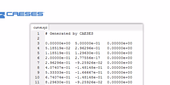
See the picture at the top of this post: Let’s say we want to create such an ASCII file that contains some simple xyz-point data of a curve that exists in your CAESES® project. For each design variant, you want to export this curve in such a format, and the file should be automatically put into the corresponding design directory of your current variant.
Define Input and Output
All you have to do is to wrap your export logic into a feature definition. Usually, features in CAESES® are handy for wrapping recurring geometry sequences, and they are heavily used in the context of parametric surface generation. However, you can also employ them for file I/O and many other things. In features, you can make use of loops and control statements (if, else, break, …) to create even complex export routines, or any other routines.
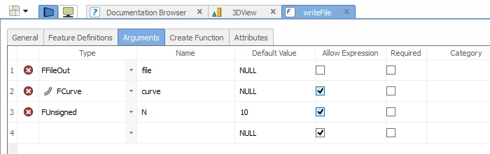
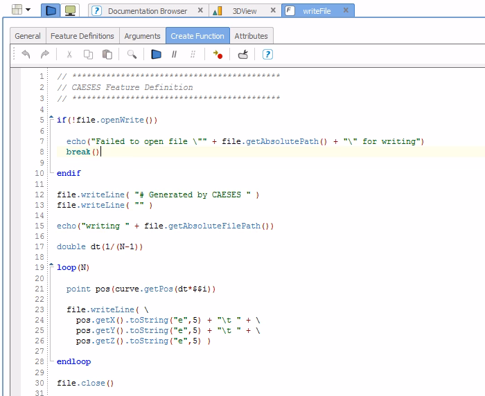
For our simple example, you first have to specify the input of your export feature, such as file name and the curve you want to export, as well as a given number of discrete points (“N”). The definition itself is rather simple and shown in the second picture below: Open the file, write out your content line by line, and finally close the file again. In a loop, the point data of the curve is calculated N‑times and written into the file using an exponential format (“e”) with a given precision (“5”).
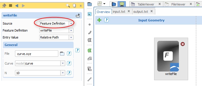
Automate with Software Connector
The software connector in CAESES® allows you to connect your external tools, i.e. to automate meshing and CFD runs. In the software connector widget, you can now create a new item (by clicking the green “+” button on the top left of the input geometry section) and choose “Feature Definition” as source. CAESES® detects all feature definitions in your project that contain file I/O commands and lists them in the next step. In our example, we have chosen the definition “writeFile”. All input arguments are then automatically given below. Just insert a file name, the curve and the number of points you want to generate. Done! Now, for each design variant that is created either manually or in an automated design study, the file “curve.xyz” is written into the correct computation directory of the current variant. You as a user don’t have to care about file management, CAESES® takes care of it!