Axial Blade Design with CAESES 4.0
With CAESES® 4.0, we have further fine-tuned our axial blade design capabilities according to the requests and wishes of our customers. We are also constantly receiving great feedback through our community forum. Thanks to everyone for contributing! We hope you will enjoy our latest blade design efforts — there you go:
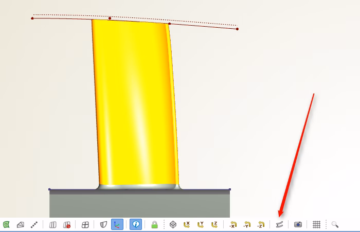
Dedicated Blade View
We are trying to keep the number of buttons as low as possible. However, with version 4.0, we decided to insert this important blade design view (ZX). So far, this has been possible only by using stored camera positions (which you still can do for custom views).
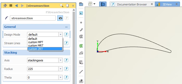
New 2D-3D Transformation
The “stream section” curve type of CAESES® maps the 2D profile into the 3D space, where hub and shroud information as well as a stacking axis are taken into account. For this transformation, you can choose between different design modes, where we’ve added the (Z,R*theta) mode for custom profiles. The “default” option is now primarily used in the context of centrifugal impeller design.
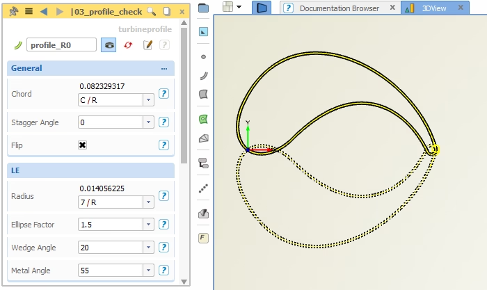
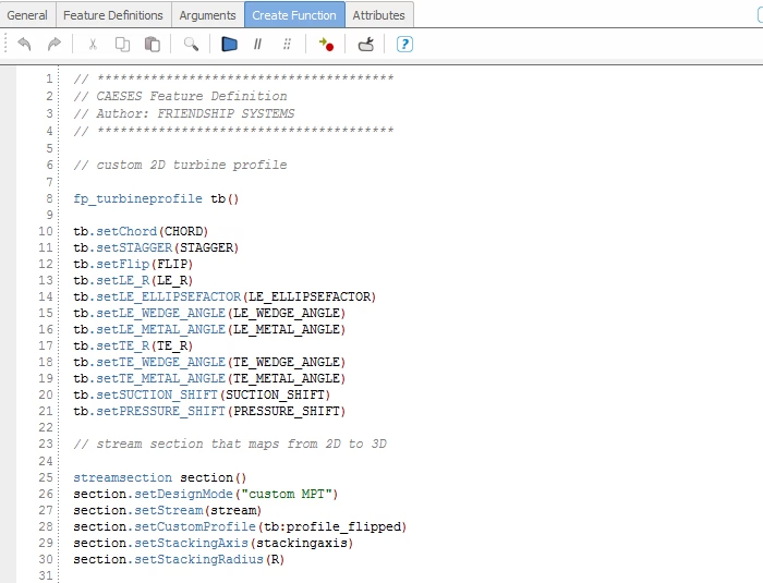
Custom Profiles
CAESES® is a powerful blade software that lets you design your own parametric 2D profiles, not matter how complex or special they are. Simply wrap such a profile in a feature definition, and then use it as input for the stream section, which maps it into the 3D space for you. Store 2D profiles on your hard disk to import and re-use it for new projects. Everything is now easier with CAESES® 4.0!
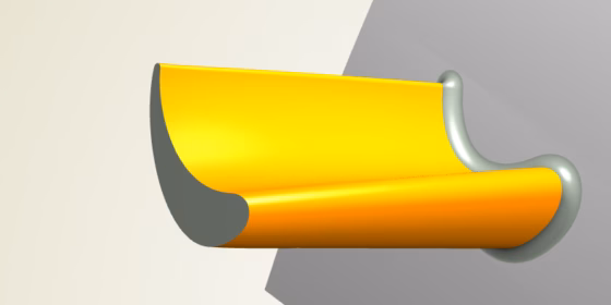
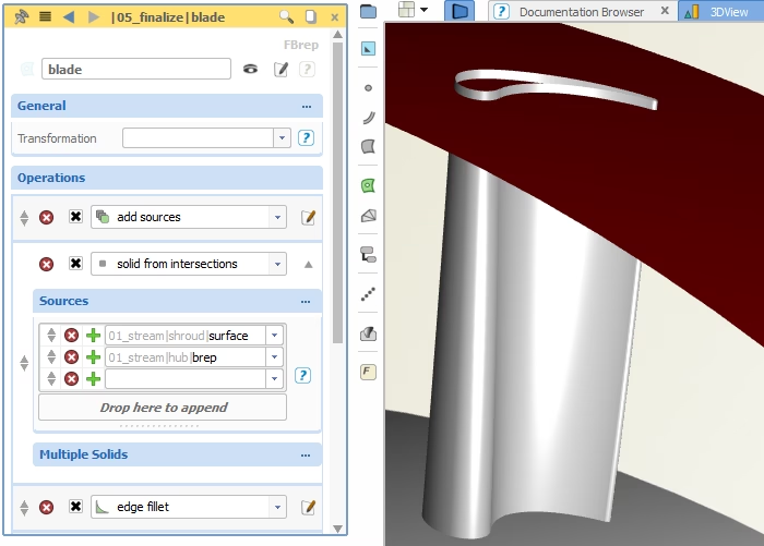
Solid From Intersections
We want you to focus on ideas for a great blade model first, this is the most exciting part! However, as soon as your parametric 3D shape is ready, you can simply apply the new brep operation “solid from intersections”. It creates a solid model by using the parametric blade as well as the hub and shroud surfaces. There is also a new mechanism to extrapolate your blade surface into the hub and shroud geometry before intersecting it.
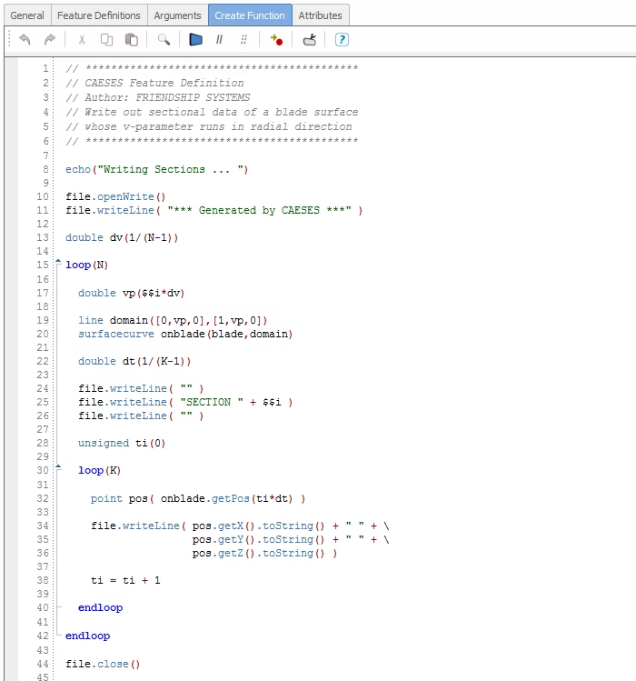
Write Your Own Exports
This has been part of CAESES® for a long time already, but let’s mention it again: We’ve noticed repeatedly that standard export formats for discrete 3D sections (point data) slightly differ from company to company. CFD engineers need this point data to continue with meshing and aerodynamic simulation. For this purpose, you can simply write your own export routine! Examples of custom exports are TurboGrid (*.curve) files or AutoGrid (*.geomturbo) files, e.g. to include endwall contouring information.
See also this post for more information.
Version 4.0 — What a Huge Task
It took us months to add a new geometry kernel, and to make it robust and smooth with version 4.0. Don’t ask the developers about it ;-) With all the new possibilities (fillets, Boolean operations, solid intersections etc.) you are perfectly equipped with everything you need to run design studies with any sophisticated CAD geometry. Version 4.0 is really a big step forward!